
How to Monitor an Automated Refrigerant Filling Process
Introduction
Automated refrigerant and coolant filling is a critical process on automotive powertrain and assembly lines. The filled volume, the tightness of the circuit, and the final liquid level all influence downstream performance and product quality. When filling is performed manually, results depend heavily on operator attention, and small deviations can go unnoticed until a leak or an incorrect charge is detected later in the line.
An automated refrigerant filling process addresses this by combining vacuum evacuation, leak testing, pressure filling, and back suction into a single controlled cycle. The role of monitoring is to confirm that each stage of that cycle has been completed within its intended conditions, and to capture the data needed for traceability.
This guide explains how to monitor an automated refrigerant filling process in practice. It covers the sequence of the filling cycle, the parameters worth watching, the role of the PLC control system, and the process conditions that indicate a stable, repeatable fill.
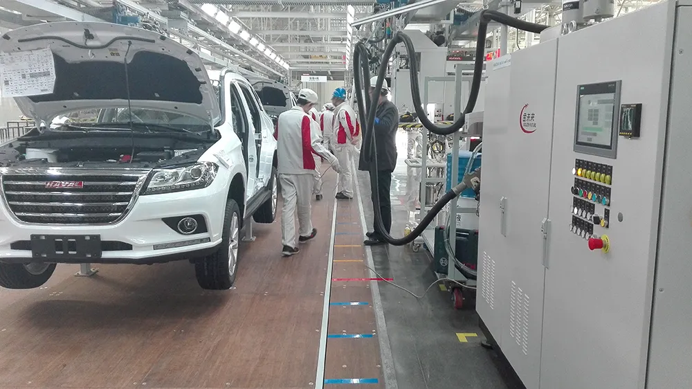
Product Overview
The Antifreeze Vacuum Filling Machine is designed for precise filling with a stable liquid level. It automates the complete coolant and antifreeze filling process, from vacuum evacuation through leak testing to pressure filling and back suction.
The machine is intended for automated coolant and antifreeze filling applications on automotive production and assembly lines. It integrates the full filling cycle into one unit, which means the monitoring task is not about watching a single filling step, but about verifying that each stage of the cycle behaves as expected.
Key equipment specifications for the machine are listed below. These values define the operating window within which monitoring takes place.
| Parameter | Specification |
|---|---|
| Filling Medium | Antifreeze / Coolant |
| Filling Volume | 1–400 L |
| Filling Pressure | 1–4 bar |
| Maximum Filling Speed | 60 L/min |
| Filling Precision | ±0.5% |
| Liquid Level Accuracy | ±2 mm |
| Measurement Display Range | 0.0–999.9 L |
| Vacuum Pump Capacity | 40–65 m³/h |
| Negative Pressure Leak Rate | ≤0.5 mbar / 60 s |
| Positive Pressure Leakage | <1.4 g/year |
| Power Supply | AC 380 V ±10%, 50 Hz ±2% |
| Equipment Dimensions | 1800 × 1000 × 800 mm (customizable) |
Working Principle
The machine uses a PLC-controlled system to automate the complete filling process. The cycle follows a defined sequence, and monitoring is organized around the same sequence.
Step 1: Vacuum Evacuation
The system first performs vacuum evacuation. Air and residual vapor are removed from the circuit before any coolant is introduced. The vacuum pump capacity of 40–65 m³/h determines how quickly the target vacuum condition can be reached.
Step 2: Leak Testing Under Vacuum and Pressure
After evacuation, the system performs leak testing under vacuum and pressure conditions. The negative pressure leak rate is specified as ≤0.5 mbar / 60 s, and positive pressure leakage is specified as <1.4 g/year. These two checks confirm circuit tightness before filling begins.
Step 3: Secondary Vacuum
Once system tightness is confirmed, a secondary vacuum is created before the coolant is introduced under controlled pressure. This step prepares the circuit for filling under controlled conditions.
Step 4: Pressure Filling
Coolant is introduced under controlled pressure within the 1–4 bar range. The maximum filling speed is 60 L/min, and filling precision is ±0.5%.
Step 5: Venting and Back Suction
Once the filling pressure reaches equilibrium, the system automatically vents to atmospheric pressure and performs back suction to remove excess coolant. This helps achieve the specified liquid level, which is held to ±2 mm, and prevents the coolant level from dropping after filling.
Monitoring note: Because the cycle integrates vacuum evacuation, leak testing, pressure filling, and back suction, monitoring should be applied to each stage rather than only to the final filled volume. A stable final level depends on the earlier stages behaving correctly.
How to Monitor the Process
Monitoring an automated refrigerant filling process means confirming that each stage reaches its intended condition and that the transition between stages occurs as designed. The following practices apply to a PLC-controlled vacuum filling machine.
1. Confirm the Vacuum Stage Before Filling
Verify that evacuation has taken place before coolant is introduced. A circuit that is not properly evacuated can trap air and affect the final charge. The vacuum pump capacity of 40–65 m³/h sets the expected pace of this stage.
2. Watch the Leak Test Result
The leak test is the primary quality gate in the cycle. Confirm that the negative pressure leak rate remains within ≤0.5 mbar / 60 s and that positive pressure leakage stays below 1.4 g/year. A failed or marginal leak test should stop the cycle before filling, because filling a leaking circuit wastes medium and can hide a defect.
3. Verify Filling Pressure and Speed
During filling, confirm that pressure stays within the 1–4 bar range and that the fill proceeds at a rate consistent with the 60 L/min maximum filling speed. The filling volume range is 1–400 L, so the expected fill time depends on the target volume for the specific application.
4. Check Filling Precision and Displayed Volume
Compare the delivered volume against the target. Filling precision is ±0.5%, and the measurement display range is 0.0–999.9 L. The displayed value is the reference for confirming that the intended volume has been delivered.
5. Confirm Venting and Back Suction
After filling pressure reaches equilibrium, the system vents to atmospheric pressure and performs back suction. Confirm that this stage completes, because it is what establishes the final liquid level and prevents the level from dropping after filling.
6. Verify the Final Liquid Level
The liquid level accuracy is ±2 mm. The final level check confirms that the combination of filling and back suction produced the specified result. This is the last verification point in the cycle.
7. Record the Cycle Data
Because the process is PLC-controlled, the conditions of each stage can be captured as part of the production record. Recording vacuum, leak test result, filling pressure, delivered volume, and final level supports traceability and makes it easier to investigate deviations.
Key Features
PLC-controlled automation of the complete coolant filling process
Integrated vacuum evacuation, leak testing, pressure filling, and back suction in one cycle
Leak testing under both vacuum and pressure conditions
Secondary vacuum before coolant introduction under controlled pressure
Automatic venting to atmospheric pressure and back suction to achieve the specified liquid level
Filling precision of ±0.5% and liquid level accuracy of ±2 mm
Filling volume range of 1–400 L and filling pressure range of 1–4 bar
Maximum filling speed of 60 L/min
Measurement display range of 0.0–999.9 L
Customizable equipment dimensions
Applications
The machine is suitable for automated coolant and antifreeze filling applications on automotive production and assembly lines. Typical settings include:
Automotive manufacturing and assembly lines requiring controlled coolant filling
Powertrain manufacturing where circuit tightness and fill accuracy matter
Automotive component production where repeatable filling is required
New energy vehicle production lines that use automated fluid filling stations, including new energy cooling systems
Intelligent factory automation environments where filling data is part of the production record
Benefits of Proper Monitoring
Improved traceability: Stage-by-stage data supports a complete production record for each fill.
Better process consistency: Confirming each stage keeps results repeatable across cycles.
Earlier defect detection: Leak testing before filling prevents medium waste and reduces the risk of a leaking circuit moving downstream.
Stable liquid level: Venting and back suction, verified by the final level check, help prevent the level from dropping after filling.
Production integration: A PLC-controlled cycle can be monitored as part of the wider assembly line process.
Why Choose KINMARK
KINMARK is a manufacturer of marking and traceability systems, servo press systems, fluid filling systems, and robot automation systems. The company was founded in 1996 and has developed its fluid filling product line alongside its work in automotive intelligent automation equipment.
The Antifreeze Vacuum Filling Machine is supported by a 12-month warranty covering the complete machine, with professional technical support and long-term maintenance service. Fast response service includes efficient after-sales support, remote diagnosis, and technical assistance. Engineers also provide equipment installation, commissioning, and operator training to help customers start production smoothly.
For manufacturers looking to monitor and control an automated refrigerant or coolant filling process, these service elements matter as much as the equipment specification, because stable filling depends on correct setup and ongoing support.
Frequently Asked Questions
What is the most important stage to monitor in an automated refrigerant filling process?
The leak test is the key quality gate. The machine tests under vacuum and pressure conditions, with a negative pressure leak rate of ≤0.5 mbar / 60 s and positive pressure leakage of <1.4 g/year. Confirming circuit tightness before filling prevents wasted medium and helps avoid passing a leaking circuit downstream.
How is the final liquid level controlled?
Once filling pressure reaches equilibrium, the system automatically vents to atmospheric pressure and performs back suction to remove excess coolant. This achieves the specified liquid level with an accuracy of ±2 mm and helps prevent the coolant level from dropping after filling.
What filling precision can be expected?
The machine has a filling precision of ±0.5%, with a filling volume range of 1–400 L and a filling pressure range of 1–4 bar. The measurement display range is 0.0–999.9 L.
Can the filling process be integrated into a production line?
Yes. The machine is designed for automated coolant and antifreeze filling applications on automotive production and assembly lines, and the complete cycle is PLC-controlled, which allows the process to be monitored as part of the line.
What support is available after installation?
The complete machine is covered by a 12-month warranty. KINMARK provides professional technical support, long-term maintenance service, remote diagnosis, and technical assistance. Engineers also handle installation, commissioning, and operator training.
Conclusion
Monitoring an automated refrigerant filling process is not limited to reading the final volume. On a PLC-controlled vacuum filling machine, the cycle moves through vacuum evacuation, leak testing under vacuum and pressure, a secondary vacuum, pressure filling, and venting with back suction. Each stage has a defined condition that can be observed and recorded.
By confirming the leak test result, the filling pressure and speed, the delivered volume, and the final liquid level, manufacturers can keep the process repeatable and traceable. The Antifreeze Vacuum Filling Machine is built to support this kind of controlled, automated filling on automotive production and assembly lines, with a filling precision of ±0.5% and a liquid level accuracy of ±2 mm.
If you're interested in any of the equipment mentioned in this article, feel free to contact our sales engineers for detailed product information and customized technical solutions.