
Antifreeze Vacuum Filling Process: Key Steps Explained
Introduction
Coolant and antifreeze filling is one of the final and most quality-sensitive operations on an automotive production or assembly line. If air remains trapped in the cooling circuit, or if the liquid level shifts after the vehicle leaves the station, the result can be incomplete filling, unstable thermal performance, and rework further down the line. To avoid these problems, many manufacturers use a vacuum-based filling approach instead of simple gravity or pressure-only filling.
The refrigerant vacuum filling process described in this article refers to the automated sequence of vacuum evacuation, leak testing, pressure filling, and back suction that is used to introduce coolant or antifreeze into a sealed circuit at a controlled liquid level. The term is often used in the context of air-conditioning and thermal management circuits, but the same working principle applies to coolant and antifreeze filling stations on automotive assembly lines. Refrigerant Vacuum Filling Machine
This guide explains the key steps of the process, how a PLC-controlled vacuum filling machine executes each step, which parameters matter during production, and where the technology fits in automotive manufacturing, new energy vehicle, and powertrain applications.
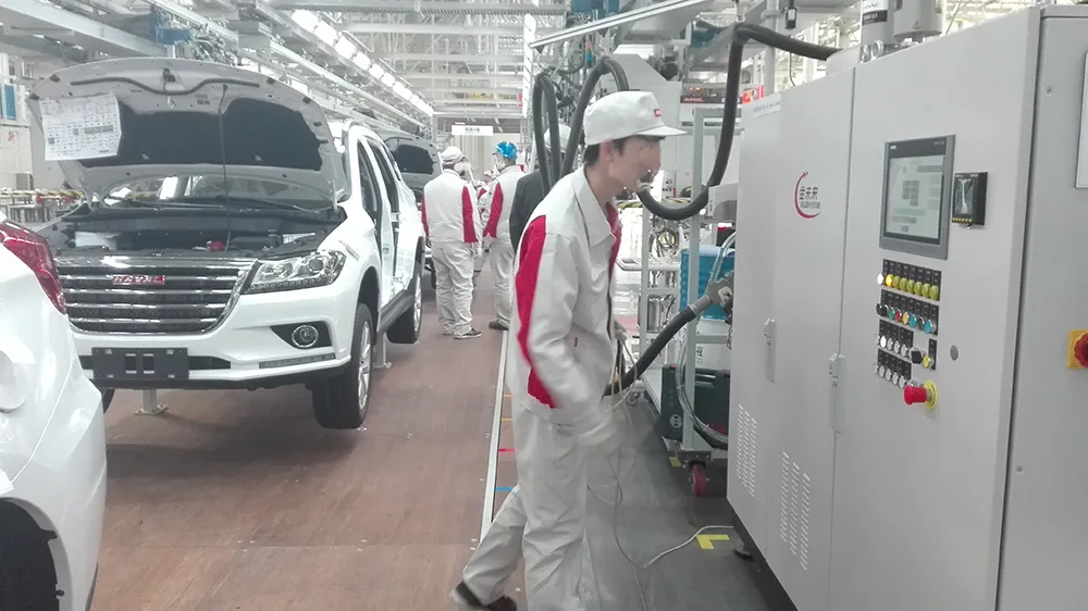
Product Overview
The Antifreeze Vacuum Filling Machine is an automated filling system designed for precise coolant and antifreeze filling with a stable liquid level. It integrates vacuum evacuation, leak testing under vacuum and pressure conditions, pressure filling, and back suction into a single controlled cycle.
The machine is built around a PLC-controlled system that automates the complete coolant filling process. Instead of relying on operator judgement to decide when a circuit is full, the system follows a defined sequence and uses measured pressure and vacuum conditions to confirm that the circuit is tight and correctly filled.
The equipment is intended for automated coolant and antifreeze filling applications on automotive production and assembly lines. Its filling volume range of 1–400 L and filling pressure range of 1–4 bar allow it to serve different circuit sizes and filling requirements within that scope. Fluid Filling Systems
Working Principle
The working principle of the vacuum filling process is based on removing air from the circuit before liquid is introduced. Air is compressible and can become trapped in high points, narrow passages, and complex cooling channels. By pulling a vacuum first, the system reduces the amount of residual air and creates a pressure difference that helps the coolant enter the circuit more completely.
According to the product description, the cycle proceeds as follows:
Vacuum evacuation: the system first performs vacuum evacuation to remove air from the circuit.
Leak testing: leak testing is then carried out under vacuum and pressure conditions to confirm system tightness.
Secondary vacuum: after tightness is confirmed, a secondary vacuum is created before the coolant is introduced.
Pressure filling: coolant is introduced under controlled pressure.
Pressure equilibrium: once the filling pressure reaches equilibrium, the system automatically vents to atmospheric pressure.
Back suction: excess coolant is removed by back suction to achieve the specified liquid level.
The purpose of the back suction step is to prevent the coolant level from dropping after filling. Without this step, residual pressure or trapped air can cause the level to settle later, creating an underfilled condition that may only be detected after the vehicle has moved on.
Process sequence in short: vacuum evacuation → leak test → secondary vacuum → pressure filling → vent to atmosphere → back suction → specified liquid level.
Key Steps of the Refrigerant Vacuum Filling Process
Step 1: Vacuum Evacuation
The first step removes air and moisture-bearing atmosphere from the circuit. The vacuum pump capacity of the Antifreeze Vacuum Filling Machine is 40–65 m³/h, which supports evacuation of the circuit before filling begins. Removing air at this stage is what allows the subsequent filling step to introduce liquid into the space that would otherwise be occupied by compressible gas. Vacuum Filling Machines
Step 2: Leak Testing Under Vacuum and Pressure
After evacuation, the system performs leak testing under vacuum and pressure conditions. This is a critical quality gate: if the circuit is not tight, filling it with coolant may lead to leakage, incomplete filling, or a fault that is difficult to trace later.
The equipment specification lists a negative pressure leak rate of ≤0.5 mbar / 60 s and a positive pressure leakage of <1.4 g/year. These values describe the leak-tightness conditions the machine is designed to evaluate during the test sequence. In production, the leak test result determines whether the circuit can proceed to filling or should be flagged for attention.
Step 3: Secondary Vacuum Before Filling
Once tightness is confirmed, a secondary vacuum is created before the coolant is introduced. This step further stabilizes the circuit conditions and prepares the system for controlled pressure filling.
Step 4: Pressure Filling with Coolant or Antifreeze
Coolant or antifreeze is introduced under controlled pressure. The filling pressure range of the machine is 1–4 bar, and the maximum filling speed is 60 L/min. The filling precision is stated as ±0.5%, which supports repeatable fill quantities across production cycles.
The filling volume range is 1–400 L, and the measurement display range is 0.0–999.9 L. These ranges make the system suitable for different circuit sizes within the stated scope.
Step 5: Venting to Atmospheric Pressure
When the filling pressure reaches equilibrium, the system automatically vents to atmospheric pressure. This controlled venting step releases the pressure built up during filling and prepares the circuit for the final level adjustment.
Step 6: Back Suction to the Specified Liquid Level
The final step is back suction, which removes excess coolant to achieve the specified liquid level. The liquid level accuracy of the machine is ±2 mm. This step is what helps prevent the coolant level from dropping after filling, a common issue when circuits are filled without a level correction stage.
Key Features
PLC-controlled automated cycle: the complete coolant filling process is automated, from vacuum evacuation through back suction.
Integrated leak testing: leak testing is performed under vacuum and pressure conditions within the same cycle.
Secondary vacuum stage: a second vacuum is created before coolant introduction to support stable filling.
Controlled pressure filling: filling pressure of 1–4 bar with a maximum filling speed of 60 L/min.
Filling precision of ±0.5%: supports repeatable fill quantities.
Liquid level accuracy of ±2 mm: achieved through automatic back suction after filling.
Measurement display range of 0.0–999.9 L: provides a clear indication of the measured volume.
Customizable equipment dimensions: standard dimensions are 1800 × 1000 × 800 mm and can be customized for line integration.
Technical Specifications
| Filling Medium | Antifreeze / Coolant |
| Filling Volume | 1–400 L |
| Filling Pressure | 1–4 bar |
| Maximum Filling Speed | 60 L/min |
| Filling Precision | ±0.5% |
| Liquid Level Accuracy | ±2 mm |
| Measurement Display Range | 0.0–999.9 L |
| Vacuum Pump Capacity | 40–65 m³/h |
| Negative Pressure Leak Rate | ≤0.5 mbar / 60 s |
| Positive Pressure Leakage | <1.4 g/year |
| Power Supply | AC 380 V ±10%, 50 Hz ±2% |
| Equipment Dimensions | 1800 × 1000 × 800 mm (customizable) |
Applications
The Antifreeze Vacuum Filling Machine is suitable for automated coolant and antifreeze filling applications on automotive production and assembly lines. Within that scope, it can be applied in areas such as:
Automotive manufacturing: coolant and antifreeze filling stations on vehicle assembly lines.
New energy vehicles: thermal management and cooling circuits that require controlled filling and stable liquid level. New Energy Cooling System
Powertrain manufacturing: filling operations where circuit tightness and fill accuracy are part of the production quality sequence.
Automotive components: filling of coolant circuits on components and sub-assemblies before delivery to the next production stage.
Intelligent factory automation: integration of automated filling and leak testing into a controlled production line.
Benefits of the Vacuum Filling Process
The vacuum-based sequence offers several practical benefits when compared with filling methods that do not remove air first:
Improved filling completeness: vacuum evacuation reduces residual air, which helps the circuit accept the intended coolant volume.
Integrated quality control: leak testing under vacuum and pressure conditions is performed before filling, so tightness is confirmed within the same cycle.
Stable liquid level: automatic venting and back suction help achieve the specified level and prevent the level from dropping after filling.
Repeatable results: PLC control and a filling precision of ±0.5% support consistent fill quantities across production cycles.
Production integration: the automated cycle can be integrated into assembly line operations, reducing manual intervention in the filling step.
Why Choose KINMARK
KINMARK is a manufacturer of marking and traceability systems, servo press systems, fluid filling systems, and robot automation systems. The company has been active in automotive intelligent automation equipment since 1996 and has established long-term cooperation with automotive manufacturers and suppliers across vehicle assembly, powertrain, automotive components, new energy vehicles, and intelligent factory automation.
For filling applications, KINMARK provides fluid filling systems with PLC-controlled process sequences, integrated leak testing, and support for automated production lines. The company also provides installation and commissioning, operator training, a 12-month warranty on the complete machine, and after-sales support with remote diagnosis and technical assistance.
For manufacturers evaluating a coolant or antifreeze filling station, the relevant questions are typically process stability, leak test integration, fill accuracy, and how well the equipment fits into an existing line. The Antifreeze Vacuum Filling Machine addresses these points through its automated vacuum filling cycle and its specified filling and level accuracy.
Frequently Asked Questions
What is the refrigerant vacuum filling process?
It is an automated filling sequence in which the circuit is first evacuated with a vacuum, then leak tested under vacuum and pressure conditions, then filled with coolant or antifreeze under controlled pressure. After the filling pressure reaches equilibrium, the system vents to atmospheric pressure and performs back suction to achieve the specified liquid level.
Why is vacuum evacuation used before filling?
Vacuum evacuation removes air from the circuit before liquid is introduced. Air is compressible and can remain trapped in the circuit, so removing it first helps the coolant enter more completely and supports a more stable filling result.
What is the purpose of the back suction step?
Back suction removes excess coolant after the filling pressure reaches equilibrium and the system vents to atmospheric pressure. This helps achieve the specified liquid level and prevents the coolant level from dropping after filling.
What are the filling specifications of the Antifreeze Vacuum Filling Machine?
The machine has a filling volume range of 1–400 L, a filling pressure range of 1–4 bar, a maximum filling speed of 60 L/min, a filling precision of ±0.5%, and a liquid level accuracy of ±2 mm. The measurement display range is 0.0–999.9 L.
Where can this filling process be applied?
It is suitable for automated coolant and antifreeze filling applications on automotive production and assembly lines, including applications in automotive manufacturing, new energy vehicles, powertrain manufacturing, automotive components, and intelligent factory automation.
Conclusion
The refrigerant vacuum filling process is built around a simple principle: remove air first, confirm tightness, then fill under controlled pressure and correct the level with back suction. Each step has a specific role in producing a complete and stable fill, and the sequence as a whole is what makes the process reliable in production.
For automotive manufacturers and component suppliers, the value of this process lies in combining filling and leak testing in one automated cycle, achieving repeatable fill quantities, and maintaining a stable liquid level after the vehicle or component leaves the station. The Antifreeze Vacuum Filling Machine applies this principle with a PLC-controlled sequence, a filling volume range of 1–400 L, a filling precision of ±0.5%, and a liquid level accuracy of ±2 mm, making it a practical option for coolant and antifreeze filling on automated production and assembly lines. Antifreeze Vacuum Filling Machine
If you're interested in any of the equipment mentioned in this article, feel free to contact our sales engineers for detailed product information and customized technical solutions.