
How Refrigerant Charging Fits into Automotive Assembly
Introduction
Fluid charging is one of the final value-adding steps on an automotive assembly line. Before a vehicle leaves the line, its thermal management and air conditioning circuits must be filled with the correct medium, at the correct volume, and with a verified leak-tight seal. Refrigerant charging in automotive assembly therefore sits at the intersection of process engineering, quality control, and production logistics.
In practice, the same process logic used for refrigerant circuits is also applied to coolant and antifreeze circuits. Both require evacuation of air and moisture, verification of circuit tightness, and controlled introduction of fluid to a defined level. This article explains how vacuum-based charging equipment works, how it integrates into assembly line workflows, and what engineers and production managers should consider when specifying fluid filling systems for vehicle and powertrain production.
Product Overview
The Antifreeze Vacuum Filling Machine is an automated filling and leak testing system designed for coolant and antifreeze circuits. It uses a PLC-controlled sequence to manage the complete filling cycle, from vacuum evacuation through leak testing, pressure filling, and back suction.
The machine is positioned for automated coolant and antifreeze filling applications on automotive production and assembly lines. It addresses a recurring industrial problem: manual or semi-automatic filling tends to leave air pockets, inconsistent liquid levels, and unverified circuit tightness. By combining evacuation, leak testing, and controlled filling in one cycle, the system supports repeatable results across a production shift.
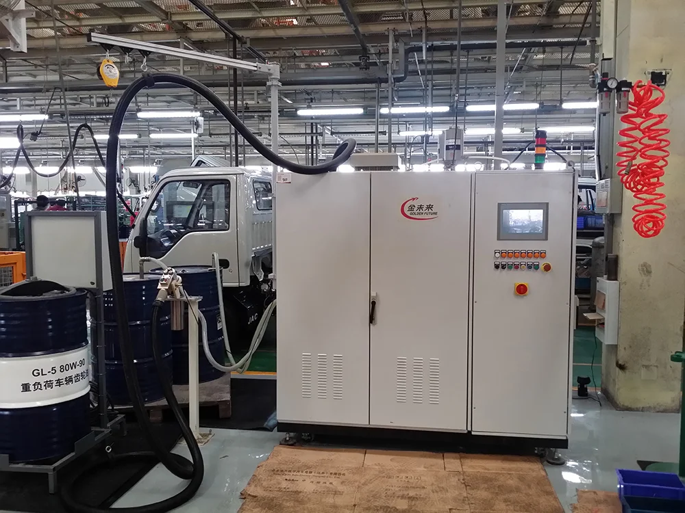
Key equipment specifications are summarized below.
| Parameter | Specification |
| Filling Medium | Antifreeze / Coolant |
| Filling Volume | 1–400 L |
| Filling Pressure | 1–4 bar |
| Maximum Filling Speed | 60 L/min |
| Filling Precision | ±0.5% |
| Liquid Level Accuracy | ±2 mm |
| Measurement Display Range | 0.0–999.9 L |
| Vacuum Pump Capacity | 40–65 m³/h |
| Negative Pressure Leak Rate | ≤0.5 mbar / 60 s |
| Positive Pressure Leakage | <1.4 g/year |
| Power Supply | AC 380 V ±10%, 50 Hz ±2% |
| Equipment Dimensions | 1800 × 1000 × 800 mm (customizable) |
Working Principle
The filling cycle follows a defined sequence controlled by the PLC system. Understanding this sequence helps explain why vacuum-based charging produces more stable results than simple gravity or pressure filling.
Step 1: Vacuum Evacuation
The system first evacuates the circuit. Removing air from the system creates the conditions needed for accurate leak detection and allows fluid to enter without trapped gas pockets.
Step 2: Leak Testing Under Vacuum and Pressure
After evacuation, the machine performs leak testing under vacuum and pressure conditions. The negative pressure leak rate is monitored at ≤0.5 mbar / 60 s, and positive pressure leakage is checked against a threshold of<1.4 g/year. Only after system tightness is confirmed does the cycle continue.
Step 3: Secondary Vacuum
A secondary vacuum is then created before the coolant is introduced under controlled pressure. This additional evacuation step further reduces residual air in the circuit.
Step 4: Pressure Filling
Coolant is introduced under controlled pressure within the 1–4 bar range. Filling volume can range from 1 to 400 L, and the maximum filling speed is 60 L/min.
Step 5: Venting and Back Suction
Once the filling pressure reaches equilibrium, the system automatically vents to atmospheric pressure and performs back suction to remove excess coolant. This is the step that helps achieve the specified liquid level and prevents the coolant level from dropping after filling.
Process note: The complete cycle integrates vacuum evacuation, leak testing, pressure filling, and back suction into one automated sequence. This is why the equipment is described as suitable for automated coolant and antifreeze filling applications on automotive production and assembly lines.
Key Features
PLC-controlled automated cycle — the complete coolant filling process is automated, reducing dependence on operator technique.
Integrated leak testing — vacuum and pressure leak testing are performed within the same cycle, before fluid is introduced.
Secondary vacuum before filling — an additional evacuation step supports more complete filling of the circuit.
Automatic venting and back suction — helps achieve the specified liquid level and prevents level drop after filling.
Defined filling accuracy — filling precision of ±0.5% and liquid level accuracy of ±2 mm support repeatable results.
Wide filling volume range — 1–400 L covers a broad range of circuit sizes.
Digital measurement display — measurement display range of 0.0–999.9 L.
Customizable dimensions — equipment dimensions of 1800 × 1000 × 800 mm can be customized for line layout requirements.
Applications
The equipment is designed for automated coolant and antifreeze filling applications on automotive production and assembly lines. Within that scope, it fits into several broader manufacturing contexts.
Automotive Manufacturing
On vehicle assembly lines, coolant circuits must be filled and verified before the vehicle moves to downstream stations. The integrated leak test within the filling cycle supports this verification step.
Automotive Components and Powertrain Manufacturing
Component and powertrain production also involves fluid circuits that require evacuation and controlled filling. The filling volume range of 1–400 L and the pressure range of 1–4 bar allow the system to be applied across different circuit sizes within these environments.
New Energy Vehicles
New energy vehicle production relies on thermal management circuits that require stable fluid levels. The back suction function, which prevents the coolant level from dropping after filling, is directly relevant to this requirement. These applications are also related to new energy vehicle cooling systems.
Intelligent Factory Automation
Because the cycle is PLC-controlled and automated, the equipment can be integrated into automated production and assembly workflows rather than being operated as a standalone manual station.
Benefits
Improved process consistency — an automated PLC sequence applies the same filling parameters across cycles, reducing variation between vehicles.
Verified circuit tightness — leak testing under vacuum and pressure conditions is completed before filling, supporting quality management at the station level.
Stable liquid level — automatic venting and back suction help achieve the specified liquid level and prevent post-fill level drop.
Reduced manual intervention — integrating evacuation, testing, filling, and back suction into one cycle reduces the number of manual steps.
Production integration — the system is intended for automated production and assembly lines, supporting line-level workflow design.
Traceable measurement — the digital measurement display range of 0.0–999.9 L gives operators a readable reference during the filling process.
Why Choose KINMARK
KINMARK (Jinan Zhongzheng Jinma Technology Co., Ltd.) was founded in 1996 and is based in the Jinan Eastern High-Tech Development Zone. The company is a developer and manufacturer of marking and traceability systems, fluid filling systems, servo press systems, and robot automation systems, and is recognized as a Shandong Province "Gazelle" enterprise and a "Specialized and Sophisticated" enterprise.
KINMARK's fluid filling product line has been applied in automotive production contexts since the company's early years. The company has established long-term cooperative relationships with automotive manufacturers including Mercedes-Benz, BMW, Toyota, Volkswagen, Tesla, GM, Nissan, FAW Hongqi, GAC, Changan Automobile, BAIC Foton, GAC Honda, Beijing Hyundai, BYD, Great Wall Motor, Geely Automobile, Chery Automobile, XPeng, and NIO. Beyond the automotive sector, KINMARK also provides automation solutions to companies such as Bosch, BorgWarner, Gree, CRRC, Meritor, and AGCO.
For fluid filling projects, KINMARK provides:
12-month warranty — the complete machine is covered, with professional technical support and long-term maintenance service.
Fast response service — efficient after-sales support, remote diagnosis, and technical assistance to support continuous operation.
Installation and commissioning — engineers provide equipment installation, commissioning, and operator training to help customers start production smoothly.
Service network — offices and maintenance centers are located in Shanghai, Beijing, Guangzhou, Changchun, Wuhan, and Chongqing.
Frequently Asked Questions
What media can the Antifreeze Vacuum Filling Machine handle?
The equipment is designed for antifreeze and coolant as the filling medium. It is intended for automated coolant and antifreeze filling applications on automotive production and assembly lines.
How does the machine prevent the coolant level from dropping after filling?
After the filling pressure reaches equilibrium, the system automatically vents to atmospheric pressure and performs back suction to remove excess coolant. This back suction step helps achieve the specified liquid level and prevents the level from dropping after filling.
Is leak testing part of the filling cycle?
Yes. The system performs leak testing under vacuum and pressure conditions after the initial vacuum evacuation. The negative pressure leak rate is monitored at ≤0.5 mbar / 60 s, and positive pressure leakage is checked against a threshold of<1.4 g/year. Filling proceeds only after system tightness is confirmed.
What are the filling volume and pressure ranges?
Filling volume ranges from 1 to 400 L, and filling pressure ranges from 1 to 4 bar. The maximum filling speed is 60 L/min, with a filling precision of ±0.5% and liquid level accuracy of ±2 mm.
Can the equipment be adapted to different line layouts?
The standard equipment dimensions are 1800 × 1000 × 800 mm, and these dimensions are customizable. The machine is powered by AC 380 V ±10%, 50 Hz ±2%. KINMARK engineers also provide installation, commissioning, and operator training.
Conclusion
Refrigerant charging in automotive assembly, and the closely related process of coolant and antifreeze filling, depends on more than simply moving fluid into a circuit. The sequence matters: evacuation removes air, leak testing verifies tightness, a secondary vacuum prepares the circuit, pressure filling introduces the medium, and back suction establishes a stable liquid level.
The Antifreeze Vacuum Filling Machine integrates these steps into a single PLC-controlled cycle, with defined parameters for filling volume, pressure, speed, precision, and leak rate. For engineers and production managers planning fluid filling stations on vehicle, component, powertrain, or new energy vehicle lines, the key question is how well the filling equipment matches the circuit, the line layout, and the quality requirements of the station. Evaluating those factors against documented equipment specifications is the practical starting point.
If you're interested in any of the equipment mentioned in this article, feel free to contact our sales engineers for detailed product information and customized technical solutions.