
How an Automotive Vacuum Coolant Filling Machine Supports Reliable Filling
Introduction
Reliable charging of refrigerant and coolant circuits is a critical step in automotive manufacturing and assembly. Whether the circuit is part of an air conditioning system, a battery thermal management loop, or a powertrain cooling circuit, the fluid must be introduced in the correct quantity, at a controlled pressure, and without trapped air or moisture. A vacuum refrigerant filling machine addresses these requirements by combining vacuum evacuation, leak testing, and pressure filling in a single automated cycle.
For engineers and production managers, the challenge is not simply moving fluid from a tank into a vehicle. It is achieving a repeatable liquid level, verifying circuit tightness, and integrating the process into a paced assembly line. This article explains how a vacuum refrigerant filling machine works, what functions it performs during a filling cycle, and where it fits in automotive production environments.
Product Overview
A vacuum refrigerant filling machine is an automated system that fills antifreeze, coolant, or refrigerant-type media into vehicle circuits using a PLC-controlled sequence. Rather than relying on gravity or simple pump transfer, the machine evacuates the circuit first, checks it for leaks, and then introduces the medium under controlled pressure.
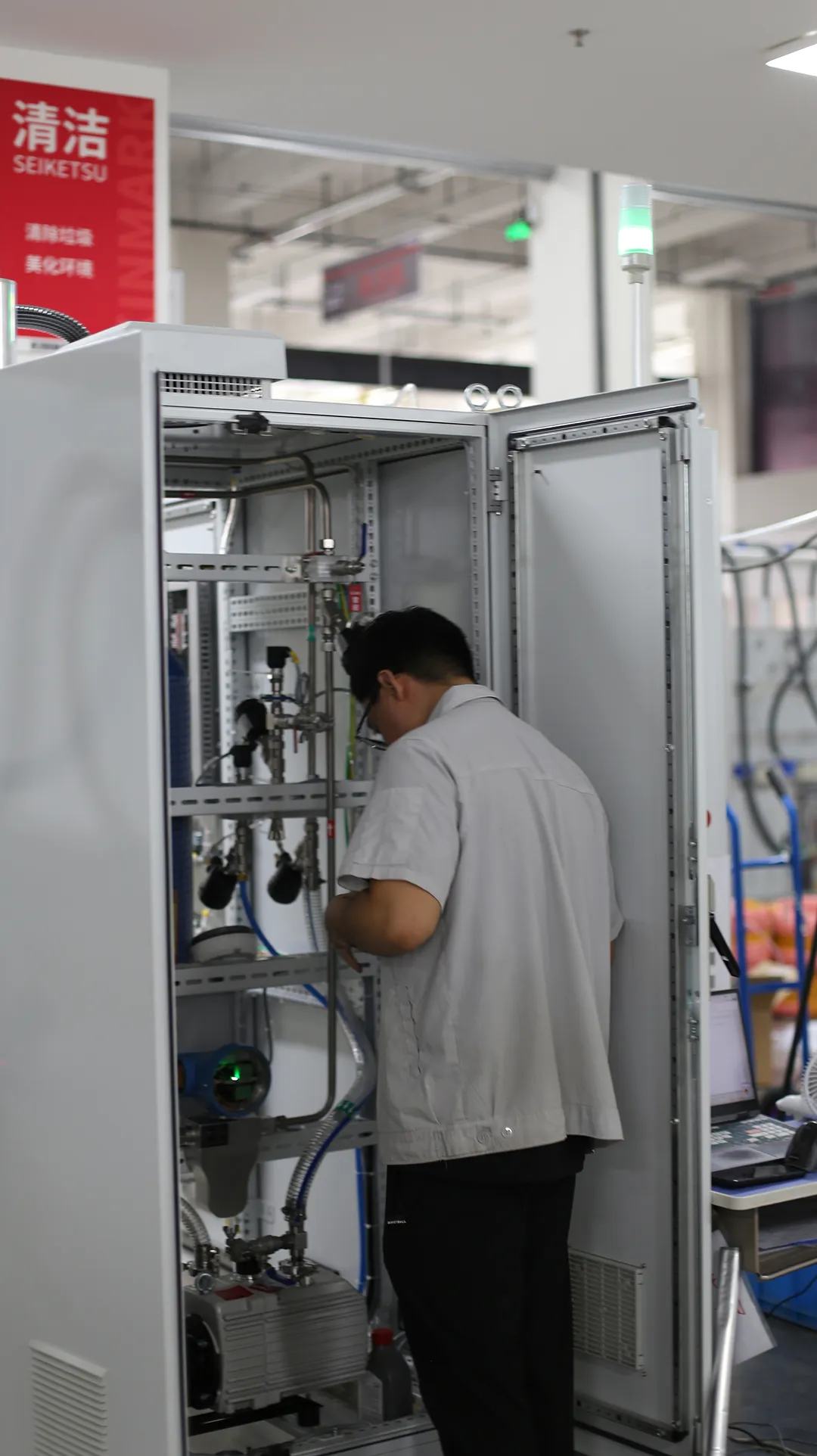
The machine is designed for automated coolant and antifreeze filling applications on automotive production and assembly lines. Its stated purpose is precise filling with a stable liquid level, supported by automated vacuum evacuation and leak testing. This combination helps prevent common filling problems such as air pockets, inconsistent fill volume, and coolant level drop after the vehicle leaves the station.
Typical configuration includes a filling medium compatible with antifreeze and coolant, a filling volume range of 1–400 L, filling pressure of 1–4 bar, and a maximum filling speed of 60 L/min. These specifications make the equipment suitable for a range of vehicle and component filling tasks where controlled delivery matters.
Working Principle
The filling cycle follows a defined sequence controlled by the PLC. Understanding this sequence helps engineers evaluate how the machine fits into a production line and how it supports process reliability.
Step 1: Vacuum Evacuation
The system first performs vacuum evacuation of the circuit. Removing air from the circuit before filling reduces the risk of trapped gas and prepares the system for leak verification. The vacuum pump capacity is specified at 40–65 m³/h.
Step 2: Leak Testing Under Vacuum and Pressure
After evacuation, the machine performs leak testing under vacuum and pressure conditions. The stated negative pressure leak rate is ≤0.5 mbar / 60 s, and the positive pressure leakage specification is<1.4 g/year. These checks confirm circuit tightness before the medium is introduced, helping avoid filling a circuit that may lose fluid later.
Step 3: Secondary Vacuum
Once tightness is confirmed, a secondary vacuum is created. This additional evacuation step further prepares the circuit before the coolant is introduced under controlled pressure.
Step 4: Pressure Filling
The coolant is then introduced under controlled pressure within the 1–4 bar range. Filling is carried out until the filling pressure reaches equilibrium, which supports consistent delivery of the medium into the circuit.
Step 5: Venting and Back Suction
Once the filling pressure reaches equilibrium, the system automatically vents to atmospheric pressure and performs back suction to remove excess coolant. This step helps achieve the specified liquid level and prevents the coolant level from dropping after filling. The liquid level accuracy is specified at ±2 mm, and the filling precision is ±0.5%.
Process note: The complete cycle integrates vacuum evacuation, leak testing, pressure filling, and back suction. Each stage is controlled by the PLC, which supports repeatable execution across production cycles.
Key Features
PLC-controlled automated cycle — the complete coolant filling process is automated, from vacuum evacuation through back suction.
Integrated leak testing — leak testing is performed under both vacuum and pressure conditions before filling.
Secondary vacuum before filling — an additional evacuation step prepares the circuit prior to coolant introduction.
Controlled pressure filling — filling pressure is adjustable within the 1–4 bar range.
Automatic venting and back suction — helps achieve the specified liquid level and prevents level drop after filling.
Stable liquid level — liquid level accuracy of ±2 mm supports consistent fill results.
Measurement display range — 0.0–999.9 L for fill volume monitoring.
Customizable dimensions — equipment dimensions of 1800 × 1000 × 800 mm are customizable.
Technical Specifications
| Filling Medium | Antifreeze / Coolant |
| Filling Volume | 1–400 L |
| Filling Pressure | 1–4 bar |
| Maximum Filling Speed | 60 L/min |
| Filling Precision | ±0.5% |
| Liquid Level Accuracy | ±2 mm |
| Measurement Display Range | 0.0–999.9 L |
| Vacuum Pump Capacity | 40–65 m³/h |
| Negative Pressure Leak Rate | ≤0.5 mbar / 60 s |
| Positive Pressure Leakage | <1.4 g/year |
| Power Supply | AC 380 V ±10%, 50 Hz ±2% |
| Equipment Dimensions | 1800 × 1000 × 800 mm (customizable) |
Applications
The machine is intended for automated coolant and antifreeze filling applications on automotive production and assembly lines. Its design supports filling tasks where vacuum evacuation, leak verification, and a stable final liquid level are required.
Relevant application areas include:
Automotive manufacturing and final assembly lines
Powertrain manufacturing and component filling
New energy vehicle thermal management and cooling circuits
Automotive component production where coolant filling is part of the process
Intelligent factory automation environments requiring integrated filling and testing
Because the equipment supports a filling volume range of 1–400 L, it can be applied to different circuit sizes within these areas, subject to the specific requirements of each production process.
Benefits
Improved traceability of the filling process — the PLC-controlled cycle executes defined steps, which supports consistent process documentation and repeatability.
Better process consistency — filling precision of ±0.5% and liquid level accuracy of ±2 mm support repeatable fill results across vehicles.
Reduced risk of trapped air and moisture — vacuum evacuation before filling helps prepare the circuit for fluid introduction.
Leak verification before filling — integrated vacuum and pressure leak testing helps identify circuit tightness issues before the medium is introduced.
Stable liquid level after filling — automatic venting and back suction help prevent the coolant level from dropping after the fill cycle.
Production integration — the automated cycle is designed for assembly line operation, supporting paced production.
Support for quality management — measurement display and defined process steps provide data that can support quality control activities.
Why Choose KINMARK
KINMARK is a manufacturer of marking and traceability systems, servo press systems, fluid filling systems, and robot automation systems. Since its establishment in 1996, the company has focused on intelligent automated equipment for the automotive industry and related sectors. Its fluid filling systems are developed for applications such as coolant and antifreeze filling on automotive production lines.
The company serves automotive manufacturing, automotive components, new energy vehicles, powertrain manufacturing, and intelligent factory automation. KINMARK maintains offices and service centers in cities including Shanghai, Beijing, Guangzhou, Changchun, Wuhan, and Chongqing, and provides installation, commissioning, and operator training as part of its service offering.
For production teams evaluating filling equipment, the relevant considerations are process fit, repeatability, and service support. The Antifreeze Vacuum Filling Machine is positioned around precise filling with a stable liquid level, supported by an automated vacuum, leak test, fill, and back suction cycle.
Frequently Asked Questions
What is the purpose of vacuum evacuation before filling?
Vacuum evacuation removes air from the circuit before the coolant is introduced. In this machine, evacuation is followed by leak testing under vacuum and pressure conditions, and then a secondary vacuum is created before filling. This sequence helps prepare the circuit for controlled fluid introduction.
How does the machine support a stable liquid level?
Once the filling pressure reaches equilibrium, the system automatically vents to atmospheric pressure and performs back suction to remove excess coolant. This helps achieve the specified liquid level and prevents the coolant level from dropping after filling. The stated liquid level accuracy is ±2 mm.
What filling media can the machine handle?
The equipment is specified for antifreeze and coolant as the filling medium. The filling volume range is 1–400 L, and the filling pressure range is 1–4 bar.
Is leak testing included in the filling cycle?
Yes. The cycle includes leak testing under vacuum and pressure conditions. The stated negative pressure leak rate is ≤0.5 mbar / 60 s, and the positive pressure leakage specification is<1.4 g/year.
Can the equipment be adapted to different production lines?
The equipment dimensions are listed as 1800 × 1000 × 800 mm and are customizable. KINMARK provides installation, commissioning, and operator training to support integration into production environments.
Conclusion
A vacuum refrigerant filling machine supports reliable charging by combining vacuum evacuation, leak testing, pressure filling, and back suction in a single PLC-controlled cycle. For automotive manufacturing and assembly, this approach helps address common filling concerns such as trapped air, inconsistent fill volume, and liquid level drop after filling.
The Antifreeze Vacuum Filling Machine is specified for antifreeze and coolant filling with a filling volume range of 1–400 L, filling pressure of 1–4 bar, filling precision of ±0.5%, and liquid level accuracy of ±2 mm. Its integrated leak testing and automatic venting and back suction functions support stable, repeatable filling results. For production teams evaluating coolant filling equipment, understanding the working sequence and matching it to line requirements is the first step toward reliable charging.
If you're interested in any of the equipment mentioned in this article, feel free to contact our sales engineers for detailed product information and customized technical solutions.